Kunci Modul dan Kolom Dukungan
Kunci Modul dan Kolom Dukungan
Satu: Modul kunci
Fungsi modul kunci adalah untuk mencegah cetakan membuka dari permukaan perpisahan selama transportasi atau penanganan, yang dapat menyebabkan kerusakan jamur atau kecelakaan keselamatan pribadi. Modul kunci tidak hanya mengunci templat yang bergerak dan tetap; Semua templat yang dapat dibuka harus dikunci.
1. Metode pemasangan modul kunci
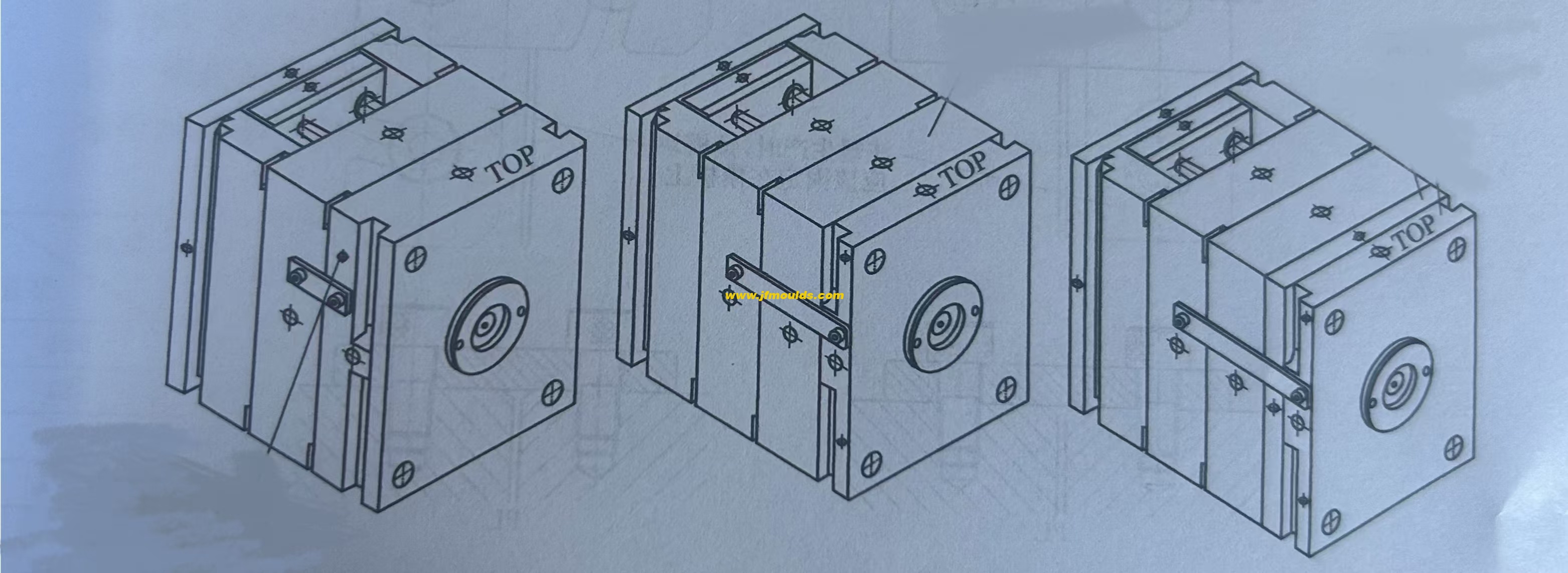
Modul kunci harus dipasang di bagian depan operator mesin cetakan injeksi.
Lubang sekrup tambahan harus dikerjakan pada pelat A cetakan yang tetap atau pelat B yang bergerak. Posisi harus didasarkan pada prinsip tidak menghambat produksi. Fungsinya adalah untuk memperbaiki dan mengunci templat selama produksi cetakan tanpa perlu dihapus.
Produsen cetakan injeksi kursi di Cina (jfmoulds.com)
2. Bentuk modul kunci
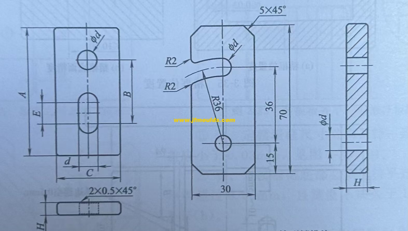
Ada dua bentuk modul kunci standar. Untuk modul kunci lubang berbentuk pinggang yang umum digunakan, kecuali diminta oleh pelanggan, modul kunci berbentuk kait umumnya tidak diadopsi.
3. Ukuran modul kunci
Ukuran modul kunci tergantung pada ukuran cetakan. Di antara mereka, A dan B tergantung pada kuantitas dan ketebalan templat yang akan dikunci, E diambil sebagai 10-15mm, dan D sama dengan diameter sekrup ditambah 1mm.
4. Perakitan modul kunci
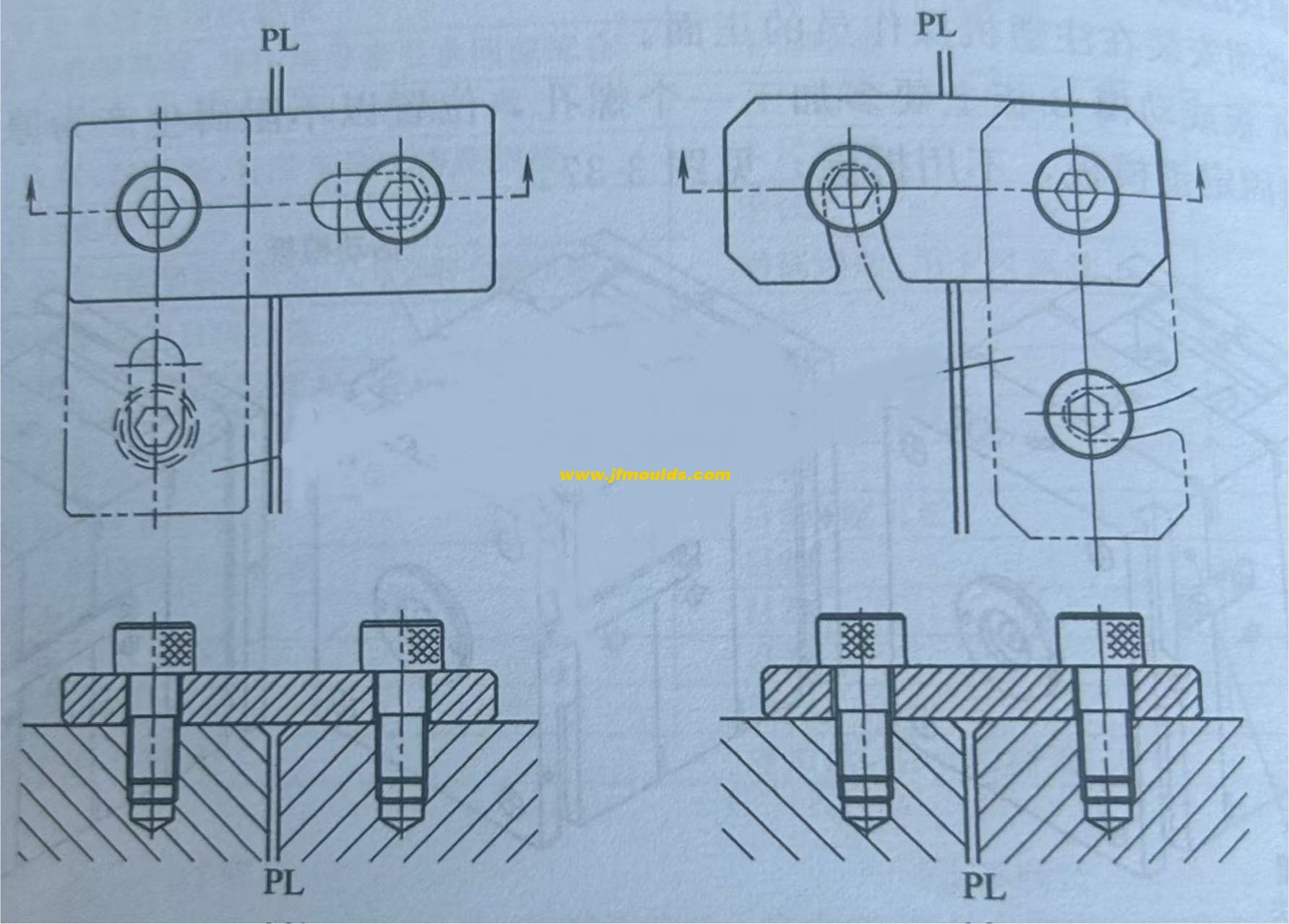
Secara umum, cetakan harus dilengkapi dengan dua modul kunci, yang terletak di kedua sisi cetakan dan diatur secara simetris.
Dua: Kolom Dukungan
Kolom pendukung, juga dikenal sebagai kolom pendukung, terutama digunakan untuk menahan gaya ekspansi yang diberikan oleh lelehan pada templat bergerak selama proses cetakan injeksi cetakan, mencegah templat bergerak dari deformasi di bawah aksi gaya ekspansi dan dengan demikian meningkatkan kekakuan cetakan. Bentuk kolom pendukung adalah silindris dan bahannya adalah 45 baja atau baja kelas kuning S50C.
1. Perakitan kolom dukungan
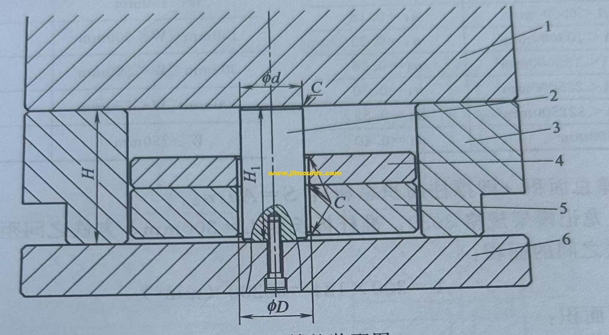
Kolom pendukung diikat ke pelat dasar cetakan yang bergerak dengan sekrup.
Tindakan Pencegahan Majelis
1. Posisi kolom dukungan harus sedekat mungkin ke tengah cetakan. Jika ruang memungkinkan, diameternya harus sebesar mungkin.
2. Chamfer tanpa tanda c = 1.
3. Ambil 1,5 hingga 2.0mm di satu sisi kelenjar antara kolom pendukung dan pelat batang push, yaitu, D = D (3 hingga 4mm).
4. Kolom pendukung harus setinggi besi. Hubungannya adalah sebagai berikut:
Ketika dimensi lebar cetakan kurang dari 300mm: H1 0,05mm;
Ketika lebar cetakan kurang dari 400mm: H1 0,1mm;
Ketika lebar cetakan antara 400 dan 700mm: H1 0,15mm;
When the width of the mold is greater than 700mm :H1=H 0.2mm
The distance between the support columns and the square irons should be no less than 25mm.
The distance between the support columns should not be less than 35mm and should not exceed 80mm
(2) Specifications and dimensions of the support columns
The specification and model representation of the support column is :SP- Diameter length.

1. Determination of the number of guard posts
If the support column is too large, it will mostly affect the rigidity and size of the push rod plate. If there are too few forks, it is difficult to ensure the rigidity of the mold. The rationality and quantity of the support columns can be determined by calculating the total area that the mold needs to support. The total area that needs to be supported can be referred to the following calculation method.
Calculate the area A between two pieces of iron: if the length of the push rod plate is 1 and the distance between the pieces of iron is W, then A- Lw.
2. The coefficient n1 is determined based on the area A between the square irons, as shown in Table 3-12.
3. Determine a certain coefficient n2 based on the distance W between the square irons.
4. Calculate the total area of the supports (I .e., the sum of the areas of the support columns) : S= an - 1-2.
The above are the calculated quantities. However, in the actual design process, due to the priority consideration of the positions and quantities of the push rods, diagonal push rods, guide columns of the push rod plate and K.O holes (the support columns must not interfere with these structures), the size and quantity of the support columns are often restricted. If the total area of the support columns is far from the calculated area, the solution is to increase the thickness of the moving die B plate by 10mm or 20mm.
Mould_Taizhou jiifeng Mould Co.,Ltd. (jfmoulds.com)

Informasi terkait
Solusi untuk garis penjepit cetakan, tanda penjepit permukaan dan posisi penjepit menempel pada cetakan
2025-08-15
Solusi untuk garis penjepit cetakan, tanda penjepit permukaan dan posisi penjepit ...
Solusi untuk masalah deformasi lentur kolom, delaminasi, pengelupasan permukaan dan sering menekan semburan kecil dalam cetakan
2025-08-18
Solusi untuk masalah deformasi lentur kolom, delaminasi, permukaan p ...
Solusi untuk tanda udara di posisi outlet air cetakan dan seret kerusakan pada posisi outlet air dari bingkai baterai
2025-08-27
Solusi untuk tanda udara di posisi outlet air cetakan dan seret kerusakan ...
Solusi untuk permukaan cetakan yang tidak rata, pemutihan posisi tulang karena udara yang terperangkap, garis udara di titik masuk lem, dan kurangnya lem
2025-08-25
Solusi untuk permukaan cetakan yang tidak rata, pemutihan posisi tulang ...
Karet elastis cetakan dan mekanisme pemisahan jarak tetap
2025-10-05
Karet elastis dari cetakan dan mekanisme pemisahan jarak tetap: Elas ...
Menjelajahi cetakan injeksi: landasan manufaktur presisi
2025-07-02
Menjelajahi cetakan injeksi: bagian utama manufaktur presisi di...
