Batasi pin dan pegas cetakan
Batasi pin dan pegas cetakan
Satu: Pin Batas
Fungsi kuku batas adalah untuk membuat celah tertentu antara pelat batang push dan pelat bawah cetakan yang bergerak, mencegah deformasi templat atau koneksi antara pelat batang dan cetakan yang bergerak
Sampah jatuh di antara cetakan pelat bawah, menyebabkan pelat batang push gagal mengatur ulang secara akurat. Batas kuku, umumnya dikenal sebagai kuku sampah, biasanya terbuat dari bahan P-20.
(1) Spesifikasi dan model pin batas
Ada dua bentuk standar pin batas.
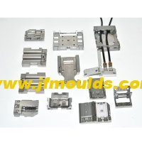
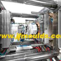
Produsen cetakan lampu mobil di Cina (jfmoulds.com)

(2) Ukuran pin batas
(3) Perakitan kuku batas
Pin batas harus dipasang pada pelat dasar cetakan yang bergerak. Untuk pin batas integral, kecocokan gangguan harus diadopsi.
② Posisi pin batas. Batas kuku harus ditambahkan di bawah semua batang reset, pada area padat batang dorong dan di bawah batang dorong yang miring untuk menahan gaya ekspansi selama injeksi cetakan.
Dua: Musim Semi

Dalam cetakan, pegas terutama digunakan sebagai daya tambahan untuk komponen bergerak seperti reset pelat batang push, penentuan posisi slider dalam mekanisme penarik inti lateral, dan jarak dan perpisahan templat yang bergerak. Karena pegas tidak memiliki dorongan yang kaku dan rentan terhadap kegagalan kelelahan, mereka tidak diizinkan untuk digunakan sendiri
Menggunakan. Mata air dalam cetakan termasuk pegas biru persegi panjang dan pegas hitam melingkar. Karena pegas biru persegi panjang memiliki koefisien elastis yang lebih besar, kekakuan yang lebih kuat dan rasio kompresi yang lebih besar daripada pegas hitam melingkar, pegas biru persegi panjang biasanya digunakan dalam cetakan.
(1) Push Plate Rod Plate Reset Spring
Dorong pelat batang push kembali ke posisi semula. Pegas reset yang biasa digunakan adalah pegas biru persegi panjang, tetapi jika cetakannya besar dan ada banyak batang dorong, itu pasti
Pertimbangkan untuk menggunakan pegas persegi panjang hijau atau berwarna kopi. Saat memilih thumbnail beban ringan, aspek-aspek berikut harus dicatat.
1. Jumlah preloading dan rasio preloading
Ketika pelat batang push kembali ke posisi semula, pegas masih perlu mempertahankan gaya elastis pada pelat batang push. Gaya ini berasal dari tekanan atas pegas, dan pra-tekanan umumnya diperlukan sekitar 10% dari panjang bebas pegas.
Jumlah preload dibagi dengan panjang bebas memberikan rasio preload. Untuk pegas dengan diameter yang lebih besar, rasio preload yang lebih kecil harus dipilih.
Saat memilih pegas pengembalian untuk pelat batang push cetakan, rasio preload umumnya tidak digunakan, tetapi jumlah preload diadopsi secara langsung. Ini dapat memastikan bahwa, di bawah kondisi dimensi berdiameter pegas yang konsisten, preload yang diterapkan pada pelat batang push tidak dipengaruhi oleh panjang bebas pegas. Preload umumnya diambil sebagai 10,0 hingga 15.0mm.
2. Jumlah kompresi dan rasio kompresi
Pegas kompresi biasanya digunakan dalam cetakan. Ketika pelat batang push mendorong bagian plastik, pegas dikompresi, dan jumlah kompresi sama dengan jarak bagian plastik didorong keluar. Rasio kompresi adalah rasio jumlah kompresi dengan panjang bebas. Secara umum, menurut persyaratan masa pakai layanan, rasio kompresi pegas biru persegi panjang adalah antara 30% dan 40%. Semakin kecil rasio kompresi, semakin lama masa pakai.
3. Jumlah dan Diameter Mata Air Reset
4. Penentuan panjang bebas pegas
① Free length calculation: The free length of the spring should be determined based on the compression ratio and the required compression amount. In the formula L free =(E P)/S
E is the stroke of the push rod plate, E= the minimum distance the plastic part is pushed out 15 to 20mm.
P represents the preload amount, which is generally taken as 10 to 15mm. It is determined based on the resistance during reset. The smaller the resistance, the smaller the preload. Usually, it can also be selected according to the size of the mold frame. For mold frames 3030(inclusive) or less, the preload amount is 5mm; for mold frames 3030 or more, the compression amount is 10 to 15mm.
S represents the compression ratio, typically taken as 30% to 40%. The free length should be determined based on factors such as mold life, mold size, and the distance between plastic parts. The standard length should be taken upwards.
If the calculated length is greater than the minimum length Lmin, the calculated length shall prevail.
The free length must be in accordance with the standard length and must not be cut for use. It is preferred to use multiples of 10
5. Assembly of the reset spring

(2) Design of the slider positioning spring in the lateral core-pulling
The spring in the lateral core-pulling mechanism mainly serves a positioning function. After the mold is opened, when the inclined guide column and the wedge block leave the slider, the spring holds against the slider and does not slide back. The commonly used diameters of springs are 10mm, 20mm and 25mm. The pressure ratio can be 12mm or 16mm, and the compression ratio can be 1/4 to 1/3. The quantity is usually two.
Calculation of the free length of the slider spring: L free two-slider stroke S×3, where S is the core-pulling distance of the slider. Freedom is the free length of the spring, and the standard length should be taken upwards.
B = Free length - preload - core-pulling distance
The preload amount can be determined through calculation: slider preload amount - pressure/elastic coefficient. The upward core-pulling pressure is the slider plus the weight of the side core-pulling. When pulling the core-pulling downward or left and right, the preload can be taken as 10% of the free length.
The preloading amount can also be based on the following empirical data
Under normal circumstances, the preload after bouncing is 5mm.
If the slider is for upward core-pulling and its mass exceeds 8 to 20kg, the preload should be increased to 10mm. Meanwhile, the total length of the spring is multiplied by the stroke of the slider, S×3.5, and then rounded up to the nearest whole number.
If the slider is for upward core-pulling and its mass exceeds 20kg, the preload should be increased to 15mm.
The spring in the slider should be prevented from popping out. Therefore, the spring assembly hole should not be too large.
When the core-pulling distance of the slider is relatively large, a guide pin should be installed.

The core-pulling distance of the slider is relatively large and it is not convenient to install guide pins. An external spring can be used for positioning. When choosing a slider spring, there are two types of springs available for selection based on different strokes: rectangular blue springs and circular black springs.
Note: The weight of the slider × the volume of the slider × the steel material
The density (the density of steel is 7.85g/cm ³)
(3) Springs between the movable plates
When a mold has two or more parting surfaces, a space-fixing parting mechanism needs to be added to the mold. Among them, the spring is one of the important parts of this mechanism. Its function is to enable the mold to open in the predetermined sequence during mold opening, with parting surfaces I and V. Here, the spring usually does not need to be in a compressed state from beginning to end like the reset spring after mold opening. The spring only needs to be pressed on this parting surface
For the first 10 to 20mm of opening, just maintain the thrust on the template. As long as this surface is opened on time, its task is completed. For the three-plate mold that usually adopts the point gate gating system, the springs used on the first parting surface are all rectangular yellow springs of $40mmX30mm. The opening springs for other molds can be selected according to specific circumstances.

Informasi terkait
Solusi untuk pembakaran gas yang terperangkap, penjepit kawat permukaan dan lem yang tidak mencukupi di kolom bagian dalam cetakan
2025-08-11
Solusi untuk pembakaran gas yang terperangkap, penjepit kawat permukaan dan lem yang tidak mencukupi saya ...
Industri cetakan injeksi: menembus hambatan teknologi dan pengaturan jejak baru manufaktur cerdas
2025-07-01
Industri cetakan injeksi: menembus hambatan teknologi dan pengaturan...
Huangyan: membangun
2025-06-22
Distrik Huangyan Kota Taizhou dikenal sebagai pulkam cetakan di Tiongkok.
Solusi untuk bubuk karet dan goresan sisi dalam pada sariawan cetakan
2025-09-03
Solusi untuk bubuk karet dan goresan sisi dalam pada sariawan mol ...
Memasuki dunia cetakan injeksi: analisis teknologi dan pengembangan industri dari berbagai perspektif
2025-06-28
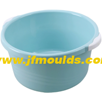
Produsen cetakan tong sampah di Tiongkok (jfmoulds.com)......
Sifat plastik dan kondisi cetakan
2025-09-13
Sifat plastik dan kondisi cetakan plastik yang berbeda memiliki ...