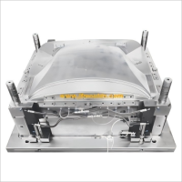
Penandaan dimensi gambar desain cetakan
Penandaan dimensi gambar desain cetakan
I. Persyaratan Umum untuk Penandaan Dimensi dalam Gambar Desain Cetakan
1. Unit yang digunakan untuk menandai dimensi: unit dimensi dalam gambar cetakan termasuk sistem metrik dan kekaisaran. Di antara mereka, negara -negara seperti Inggris, Amerika Serikat, Kanada, India, dan Australia menggunakan sistem kekaisaran, sementara Cina menggunakan sistem metrik. Namun, jika pelanggan berasal dari salah satu negara di atas, disarankan untuk menggunakan sistem kekaisaran. Selain itu, banyak bagian standar dalam cetakan (seperti sekrup, batang dorong, dll.) Ada di unit kekaisaran. Oleh karena itu, bahkan jika dimensi lain berada dalam sistem metrik selama desain cetakan, dimensi bagian -bagian standar ini masih ditandai dalam unit kekaisaran.
2. Ketepatan yang diadopsi saat menandai dimensi.
Dimensi linier: Sistem metrik menggunakan dua tempat desimal x.xxmm, dan sistem kekaisaran menggunakan empat tempat desimal x.xxxxin.
Sudut: Gunakan satu tempat desimal: x.x °.
3. Referensi dimensi dalam gambar cetakan
A. Referensi Produk (Bagian Plastik): Referensi berdasarkan gambar produk pelanggan. Semua dimensi rongga dan inti harus didasarkan pada referensi bagian plastik sebagai referensi desain.
Dimensi inti dan rongga dalam gambar desain cetakan harus sesuai satu-ke-satu dengan yang ada dalam gambar produk.
B. Referensi perakitan cetakan: Umumnya, pusat basis cetakan diambil sebagai referensi perakitan. Semua dimensi yang terkait dengan perakitan dasar cetakan, seperti lubang sekrup dan lubang air pendingin, harus didasarkan pada referensi perakitan sebagai referensi desain.
C. Referensi Proses: Referensi yang ditentukan berdasarkan persyaratan pemrosesan dan pengukuran bagian cetakan, seperti counterbore lubang sisipan harus didasarkan pada permukaan bawah
Metode pemilihan referensi dimensi untuk gambar cetakan adalah sebagai berikut
A. Dalam tampilan sectional, permukaan perpisahan diambil sebagai referensi, dan simbol referensi ditambahkan secara bersamaan. Terkadang, insinyur produk mungkin memerlukan referensi berdasarkan gambar bagian plastik. Dalam kasus seperti itu, referensi bagian plastik bertepatan dengan itu dalam gambar cetakan
B. Di lantai, situasinya agak rumit dan harus diperlakukan secara berbeda.
Jika bagian plastik simetris, gunakan dua baris tengah sebagai referensi dan tambahkan simbol referensi secara bersamaan.
Jika hanya satu sumbu yang simetris sedangkan yang lain asimetris, dan jika ada posisi kolom, pusat kolom harus diambil sebagai referensi. Jika tidak ada posisi kolom, ambil garis lurus yang lebih panjang atau tepi lurus sebagai referensi.
Jika kedua sumbu asimetris, pilih posisi kolom atau sisi lurus sebagai referensi.
Pilihan referensi dimensi yang benar adalah kondisi penting untuk memastikan persyaratan desain bagian -bagian dan memfasilitasi pemrosesan dan pengukuran.

Produsen cetakan kipas di Cina (jfmoulds.com)
4. Dimensi struktur yang sama harus seragam dalam upaya yang berbeda. Misalnya, tanda seragam sesuai dengan ukuran ujung yang besar. Jika perlu, sudut demolding juga harus ditandai, seperti 50 ± 3 °. Untuk dimensi iga penguat (tulang rusuk) dan lubang, hanya ukuran tengah, lebar, kedalaman, dan diameter yang perlu ditandai. Sudut demolding harus ditandai secara terpisah.
5. Posisi dan ukuran lubang batang dorong hanya perlu ditandai pada gambar sisipan cetakan dalam. Mereka tidak perlu ditandai pada pelat pengikat batang dorong atau gambar template, tetapi diameter lubang batang push harus ditentukan.
6. Untuk bagian mesin CNC, tidak perlu menandai semua dimensi. Hanya data referensi penting dan data inspeksi yang perlu ditandai.
7. Dimensi utama yang ditandai pada sisipan yang bergerak dan tetap adalah: pemotongan kawat; Sekrup, lubang air pendingin, lubang batang dorong; Perbedaan tinggi dari permukaan perpisahan; Dimensi yang cocok dari bentuk, dll. Untuk kejelasan, di atas dapat ditandai pada satu atau lebih gambar.
8. Untuk dimensi kawat-potong, hanya dimensi utama yang harus ditandai. Untuk kontur kompleks, bagian kawat-potong dapat disalin dan ditarik secara terpisah, dan dicatat pada gambar asli.
9. Basis bekisting non-standar perlu ditandai dengan posisi dan dimensi lubang sekrup tipe template, batang reset, pin pemandu, dll., Serta dimensi deteksi NC dari bingkai bekisting yang bergerak dan tetap. Namun, basis bekisting standar tidak perlu ditandai (dan pin pemandu, batang reset, dan pin pemandu pelat batang dorong tidak lagi dipesan di bagian standar).
Saat menandai posisi pemrosesan elektroda iga penguat, hanya perlu untuk menandai posisi tengah elektroda.
Mould_Taizhou jiifeng Mould Co.,Ltd. (jfmoulds.com)
Ii. Requirements for Dimension Marking of Assembly Drawings
1. The ranking map adopts the coordinate annotation method, with the center of the mold as the coordinate origin. The sectional view adopts linear dimensioning.
2. The assembly drawing mainly marks the following dimensions.
a. Dimensions of the connection parts of the injection molding machine;
b. The dimensions of all parts that are not separately drawn in the part drawing (mainly the processing part of the mold frame), but the positions of the standard holes on the mold frame may not be marked
c. Position and size of each cavity, and try to take the nearest whole number;
d. The position of the gate and the gate sleeve screws;
e. The size of the template and the size and position of the inner mold inserts;
f. The position and size of the lateral core-pulling mechanism and its accessories;
8. The position and size of the positioning block;
h. Location, specification and number of cooling water holes;
The diameter and position of holes i.K.O;
J. The length and size of the guide pins and guide sleeves of the push rod plate;
k. Position and diameter of the support columns (S.P);
1. The diameter and length of the reset spring, the depth and diameter of the spring hole, and the spring specification should be marked;
m. The diameter and thickness of the limit nail;
n. The position and length of the spacing parting mechanism in the three-plate mold and the two-plate half-mold.
Three: Requirements for dimension marking of parts
1. Correct: Dimensional marking should comply with the basic provisions of the national standard "Mechanical Drawing"
2. Completeness: Dimensional annotations must ensure that all production activities in the factory can proceed smoothly and facilitate reference and search based on the drawings.
3. Clarity: The size configuration should be uniform and standardized
4. Reasonable: The dimensional marking should comply with the design and process requirements to ensure the performance of the mold.
5. For parts with a slope, the "large" and "small" should be noted beside the dimension marking to indicate the dimensions of the large and small ends.
6. Basic Requirements: The maximum external dimensions must be directly marked on the drawing. If a closed dimension chain is generated, parentheses can be added to the maximum external dimension.
7. Dimensions should be marked outside the view as much as possible to avoid the intersection of dimension lines, dimension numbers and the contour lines of the view.
8. The diameter dimensions of concentric cylinders are best marked on non-circular views
9. Parallel dimensions should be arranged in order of size, with smaller dimensions inside and larger dimensions outside, and their dimensions should be adjusted accordingly
10. The dimension lines should be neatly arranged, and they should be placed on the same side as much as possible. It is best to arrange the relevant dimensions in a straight line. The size numbers are staggered. In densely populated areas, the markings should be enlarged to avoid misunderstandings.
11. Important positioning dimensions in the cavity, such as holes, ribs, and grooves, should be directly marked on the reference.
12. All structures must have positioning and shaping dimensions. For the positioning dimensions of holes, ribs and grooves, the center line should be taken as the standard.
13. When marking the dimensions of sectional views, to ensure clarity, clarity and neatness, the inner and outer dimensions should be marked on both sides respectively.
Four: Examples of Dimension Marking on Mold Design Drawings
(1) Examples of dimension marking on mold assembly drawings: Due to the large number of dimensions to be marked on the assembly drawing, for the sake of clarity, in the actual working process, the main section views in the assembly drawing are not marked with section lines.
(2) An example of dimension marking for the B board of the moving mold
The structure of the moving die B plate includes: die frame, cooling water circuit, screw holes, push rod (push tube) holes, reset rod holes, holes of the spacing and parting mechanism, and sometimes a lateral core-pulling mechanism, etc. An example of dimension marking is shown in Figure 1-27. The X and Y directions are marked by the coordinate method, with the center line of the mold as the reference. The height dimensions are marked using the linear marking method, with the bottom surface of the template as the reference. Different push rod through holes are represented by different symbols, and their sizes and quantities are listed together
(3) Examples of dimension marking for fixed mold A plates
The marking method for Board A is the same as that for board B
(4) Examples of internal mold insert dimension marking: Generally, insert diagrams are divided into insert screw hole diagrams, cooling water channel diagrams, and insert processing diagrams. The
shape of the insert is simple. The screw holes, cooling water circuit diagram and processing drawing are reflected on the same drawing. Precautions when marking the insert:
1. The direction and reference Angle should be accurately marked on the die side.
2. Express the drawing completely with the fewest views, and mark the dimensions of a shape as clearly as possible on one view.
3. The surfaces that are bumped through and rubbed through should be marked with words.
4. The parting surfaces should be marked according to the positions on the assembly drawing. The reference angles should be specified and the references should be consistent with those on the assembly drawing.
5. For quenched inserts, the draft Angle of the inner mold insert forming surface should be indicated. If the draft Angle of the cavity is 1.5°, the marked size should be the large head (end) size.
Informasi terkait
Diversifikasi perusahaan cetakan injeksi
2025-06-28
Diversifikasi cetakan injeksi enterprise1. Cetakan otomotif: lekukan kemudi...
Cetakan injeksi: Pembuat tidak terlihat di lokakarya
2025-07-09
Cetakan injeksi: Pembuat tidak terlihat di workshopI. Kesan pertama dari th...
Pencetakan kue dan cahaya dan bayangan cetakan
2025-08-04
Permukaan memanggang pencetakan dan cahaya dan bayangan kue jamur dan p ...
Peralatan utama di bidang logistik dan pergudangan
2025-06-29
Peralatan utama di bidang logistik dan produsen cetakan pergudangan di...
Dari prinsip ke aplikasi, pahami "shaping master" ini dalam industri
2025-07-16
Dari prinsip ke aplikasi, pahami "shaping master" ini dalam industri...
Kolom sekrup cetakan rentan terhadap kerusakan dan tanda las/penyusutan
2025-08-07
Kolom sekrup cetakan rentan terhadap kerusakan dan tanda las/shrinkagethe sc ...


