Mekanisme penarik inti lateral dari
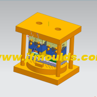
Mekanisme penarik inti lateral dari "kolom pemandu miring penggeser"
I. Klasifikasi Mekanisme Pengetikan Lateral dan Penarik Inti
Menurut karakteristik strukturalnya, mekanisme penarik inti lateral diklasifikasikan ke dalam enam kategori utama berikut.
Mekanisme penarik inti lateral dari "kolom pemandu miring penggeser".
2. Mekanisme penarik inti lateral "pin geser geser".
3. Mekanisme penarik inti lateral dari "balok berbentuk T penggeser".
4. Mekanisme penarik inti lateral "silinder hidrolik penggeser".
5. Mekanisme penarik inti lateral atas yang miring.
6. Mekanisme penarik inti lateral dari penggeser miring.
Dua: Sisi lateral "kolom pemandu miring penggeser"
Desain kolom pemandu miring dan blok tekanan kolom pemandu miring

Produsen cetakan injeksi tutup botol di Cina (jfmoulds.com)
Sudut Kemiringan a
Dalam keadaan normal, untuk a=15° hingga 25°, sudut yang umum digunakan adalah 18° dan 20&derajat; dalam kisaran ini. Semakin kecil a, semakin baik, karena semakin kecil a, semakin kecil torsi yang ditanggung oleh kolom pemandu miring, dan semakin kecil gaya gesek yang ditanggung oleh bahu penggeser.
2. Ketika jarak tarikan inti kecil dan penggesernya relatif tinggi, sudut kemiringannya. Nilai yang lebih kecil dapat diambil, tetapi nilai minimumnya tidak boleh kurang dari 10°. Ketika jarak tarikan inti besar, dimensi tinggi penggeser kecil, dan gaya penjepitan bagian plastik pada tarikan inti lateral juga kecil, sudut kemiringannya. Nilai yang lebih besar dapat diambil, tetapi nilai maksimumnya tidak boleh melebihi 30°
Ukuran a bergantung pada jarak tarikan inti lateral dan tinggi penggeser, dan tidak bergantung pada jarak lontar bagian plastik. Secara umum, dengan alasan memenuhi persyaratan jarak tarikan inti lateral, kepala kolom pemandu miring harus sedekat mungkin dengan permukaan bawah penggeser. Jika kolom pemandu miring terlalu pendek dan kepalanya jauh dari permukaan bawah penggeser, penggeser akan terkena torsi yang relatif besar selama penarikan inti. Torsi ini akan meningkatkan gesekan antara bahu penggeser dan blok tekanan atau slot-T, dan setidaknya mempercepat keausan permukaan gesekan. Dalam kasus yang parah, hal ini dapat menyebabkan penggeser "macet" dan mencegah inti ditarik keluar. Oleh karena itu, pada tahap awal penarikan inti, panjang kontak antara kolom pemandu miring dan lubang penggeser tidak boleh kurang dari dua pertiga panjang lubang miring penggeser. Sebaliknya, jika pin pemandu miring terlalu panjang dan perlu diperpanjang secara signifikan melampaui permukaan bawah penggeser, seiring dengan berlangsungnya proses penarikan inti, karena bertambahnya panjang lengan tuas, torsi yang ditanggung oleh pin pemandu miring akan menjadi semakin besar, yang pada akhirnya menyebabkan pembengkokan dan deformasi pin pemandu miring. Jika dimensi tinggi penggeser kecil karena jarak tarikan inti yang besar, kepala kolom pemandu miring harus melampaui permukaan bawah penggeser. Direkomendasikan agar panjang yang diperpanjang kurang dari sepertiga panjang lubang miring pada penggeser.

(2) Talang e pada bagian atas kolom pemandu miring
e harus lebih besar atau sama dengan sudut kemiringan a dari kolom pemandu miring untuk memastikan bahwa terdapat faktor keamanan yang cukup ketika kolom pemandu miring dimasukkan ke dalam lubang miring pada penggeser. Ketika ≥18°, kepala kolom pemandu miring harus sebisa mungkin tidak berbentuk setengah lingkaran.
(3) Panjang L kolom pemandu miring dapat dihitung berdasarkan rumus dasar fungsi trigonometri :L=L1 L2=S/sina H/cosa
H Ketebalan pelat tetap; Jarak tarikan inti S; Sudut kemiringan kolom pemandu miring.
Tiga: Desain Blok Tekanan Slider dan Slider
(1) Panduan penggeser
Hal-hal berikut harus diperhatikan saat mendesain slider
Pengoperasian penggeser harus lancar dan aman, memastikan tarikan inti lateral yang mulus tanpa gangguan apa pun. Kesenjangan dalam alur geser harus seragam, tanpa ada kelonggaran atau kekencangan yang berlebihan. Toleransi kesesuaian antara penggeser dan dudukan geser adalah H7/f7.
2. Oil grooves should be provided on the sliding surface of the large slider, and there must be cooling water channels
When the sliding stroke of the slider is too long, the guide groove must be extended on the mold base. Generally, the length of the sliding part should be about 1.5 times the height. When extracting the core, the length of the slider beyond the mold frame should not exceed one quarter of the slider's length; otherwise, the guide slide groove should be added
Long.
4. The wedge block of the slider must be inserted into the lower die for locking, with an insertion depth of 10 to 20mm and a locking Angle of 5° to 10°.
The design considerations for the slider pressure plate are as follows.
The material of the pressure plate is 718.
2. Surface ammonia infiltration treatment.
3-edge chamfer C1.
4. Processing oil grooves on sliding mating surfaces.
5. Selection of the pressure plate
a. Standard specifications should be given priority for the pressure plate, followed by the "7" shape
B. The upper end face of the pressure plate should be as flush as possible with the template surface to ensure the mold's aesthetic appearance
c. The pressure plate should be avoided from being pressed simultaneously on the inner mold inserts and the template as much as possible.
d. To prevent deformation, the length of the pressure plate should be controlled under 200mm as much as possible.
(2) Positioning of the slider during mold closing
1. General requirements for positioning
A. The positioning surface should be selected as a plane.
B. The positioning surface should be selected on relatively fixed parts, such as moving and fixed mold inserts, mold bases, etc., and must not be selected on sliders and movable inserts
c. When the slider is used for relative positioning, the slope of the positioning surface should be more than 5° on one side
d. The positioning requirements for the fixed mold slider are high because wire clamping can affect the appearance of the plastic part, so more attention should be paid. The positioning method is basically the same as that of the moving mold slider.
2. For individual sliders, the sliders shown in (a), (B ), and (c) have good positioning effects.
3. For the Haff slider (also known as the split slider). The following points should be noted when designing.
A. Each slider must have a reliable positioning. Generally, it is positioned by inserts. In cases where inserts cannot be used for positioning, separate positioning blocks should be adopted for positioning.
B. It is strictly prohibited to directly position the Haff slider with circular cores, push rods, push tubes or small inserts (these parts are prone to deformation under force).
c. There must also be a process positioning block between the two sliders to ensure that the plastic part does not grade at the wire clamping point.
d. It is essential to ensure that the inner mold inserts have sufficient positioning strength in the sliding direction.
e. The slider is not precisely positioned by directly using the arc surface of the moving mold insert. Therefore, a positioning block must be added to the insert (the positioning block is inserted into the mold base).
Komoditas mould_taichu jiifeng Mould Co.,Ltd. (jfmoulds.com)
Informasi terkait
Solusi untuk tanda udara di posisi outlet air cetakan dan seret kerusakan pada posisi outlet air dari bingkai baterai
2025-08-27
Solusi untuk tanda udara di posisi outlet air cetakan dan seret kerusakan ...
Solusi untuk masalah penjepitan kawat, menjepit deformasi pull-over posisi dan tanda udara dalam cetakan
2025-08-12
Solusi untuk masalah penjepitan kawat, menjepit posisi pull-over deformat ...
Solusi untuk bubuk karet dan goresan sisi dalam pada sariawan cetakan
2025-09-03
Solusi untuk bubuk karet dan goresan sisi dalam pada sariawan mol ...

Kekasaran permukaan bagian plastik dan pemilihan mesin cetakan injeksi
2025-09-18
Kekasaran permukaan bagian plastik dan pemilihan mesin cetakan injeksi1 ....
Wawasan mendalam ke dalam industri cetakan injeksi: iterasi teknologi, lanskap pasar, dan Paradigms baru untuk pengembangan berkelanjutan
2025-07-03
Wawasan mendalam tentang industri cetakan injeksi: iterasi teknologi, Mar.
Memasuki dunia cetakan injeksi: analisis teknologi dan pengembangan industri dari berbagai perspektif
2025-06-28
Produsen cetakan tong sampah di Tiongkok (jfmoulds.com)......