Bagian standar cetakan
Bagian standar cetakan
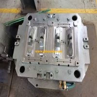
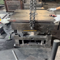
1 bingkai cetakan
Rakitan atau komponen cetakan standar prefabrikasi memberikan kenyamanan besar bagi produsen cetakan. Basis cetakan standar terdiri dari cetakan setengah bawah dan cetakan setengah atas yang dilengkapi dengan pin pemandu.
Pada hari -hari awal, kombinasi template hanya termasuk pin pemandu pelat ejector dan pin panduan samping dari cetakan tetap. Saat ini, basis cetakan lengkap dapat dibeli.
Produsen cetakanSekarang dapat fokus pada pembuatan komponen cetakan, seperti gigi berlubang. Bagian standar telah sangat mengurangi jangkauan pemrosesan kedalaman dan waktu pemrosesan dalam pembuatan cetakan.
Saat ini, bingkai bekistis standar dengan ukuran berbeda tersedia untuk dibeli, dengan dimensi hingga 796mmx996mm, dan ketebalan bekornya bervariasi dari 10 hingga 196mm. Kualitas baja juga dapat dipilih.
Semua permukaan setiap templat adalah ground, dengan paralelisme permukaan mencapai 0,008/100mm dan toleransi ketebalan mulai dari +0,05 hingga 0,25mm. Dengan konfigurasi seperti itu, produsen cetakan tidak perlu memproses ulang templat. Templat berbagai ukuran semuanya dilengkapi dengan komponen panduan yang diperlukan, seperti tiang panduan, lengan pemandu dan lengan.
Berbagai runner panas dan seri nozzle, termasuk sirkuit lebur dan kontrol suhu, telah memperkaya berbagai bagian standar.

Mould_Taizhou jiifeng Mould Co.,Ltd. (jfmoulds.com)
2. Komponen penuntun cetakan
Untuk mencegah sisipan dan inti di dalam cetakan rusak selama penutupan cetakan, komponen penuntun cetakan perlu digunakan. Untuk cetakan kecil dan ringan, pin pemandu dan lengan pemandu biasanya digunakan.
Semua komponen penuntun cetakan perlu dikeraskan. Setelah mereka dipakai, mereka bisa diganti. Untuk mencegah bagian plastik terkontaminasi oleh minyak, komponen penuntun biasanya beroperasi tanpa minyak pelumas. Produsen suku cadang standar dapat memberikan lengan pemandu yang melumasi sendiri dan bebas perawatan, sehingga menghilangkan kebutuhan minyak atau minyak. Komponen penuntun dapat digunakan dalam kondisi di mana suhu cetakan dapat mencapai hingga 200 ° C.
Bergantung pada persyaratan penggunaan yang berbeda, unit penentuan posisi bundar atau pusat persegi dapat digunakan. Komponen penentuan posisi pusat khusus dapat menghilangkan kekuatan yang tidak seimbang pada komponen penuntun selama penutupan cetakan dan mencapai kesesuaian ketat presisi tinggi.
Untuk cetakan berukuran sedang dan besar, disarankan untuk memberikan dukungan untuk cetakan melalui mesin cetakan injeksi. Dengan blok pendukung, cetakan dapat didukung oleh kolom hijau mesin cetakan injeksi atau geser di sepanjang rel pemandu templat mesin.
3 komponen demolding
Komponen demolding termasuk pin ejector, inti teleskopik, slider, blok penjepit dan berbagai bentuk kunci tepi.
Pin ejector harus dipilih dengan diameter yang lebih besar dan mampu memberikan kekuatan demolding yang cukup untuk produk. Dorongan pin ejector harus lebih besar dari adhesi antara produk dan rongga. Jika adhesi terlalu besar, deformasi atau kerusakan bagian cetakan injeksi sering terjadi selama demolding. Posisi di mana pin ejector diatur harus menghindari gaya demolding yang hanya bekerja pada keliling bagian cetakan injeksi.
Inti teleskopik
Untuk bagian -bagian demolding dengan peningkatan internal atau benang internal, inti teleskopik harus digunakan. Inti ini telah dikeraskan, dan kecuali untuk bagian -bagian berulir yang perlu diproses, bagian lain dapat dipasang kapan saja.
Slider, pegang blok perakitan dengan erat
Demolding terbalik eksternal biasanya bergantung pada komponen yang bergerak secara lateral, termasuk slider, blok penjepit dan penarik inti silinder.
Dalam cetakan dengan beberapa permukaan perpisahan, kunci tepi diperlukan untuk membuka permukaan perpisahan sekunder.
4 aksesoris pendingin cetakan
Untuk mencapai pendinginan cetakan yang efektif, beberapa aksesori standar yang relevan dapat digunakan. Seperti air cepat, sambungan pipa minyak, inti yang melakukan panas, elemen pengalihan dan inti berulir.
Konektor cepat
Standard parts manufacturers can provide a complete range of water/oil quick couplings. The most commonly used diameters are 9mm, 13mm and 19mm. The diameter of the fine and small core can even reach 5mm.
Quick couplings can be equipped with control valves or not. The characteristic of a valveless system is that the pressure drop in the cooling water channel is very small, while in a valveless system, the cooling medium will not be lost when the joint is loosened, and it can prevent corrosion caused by oxygen infiltration.
Threaded core
The threaded core is precisely fitted into the inner hole of the core, allowing the cooling medium to flow smoothly along the inner wall and ensuring good heat transfer. There are two types of threaded cores: single-ended and double-ended. In a single-ended threaded core, the cooling medium is introduced through a hole in the core and then flows back along the threaded ring. And the double-ended threaded core is composed of.
The cooling medium is introduced through the first helical channel and discharged through the second helical channel.

Komoditas mould_taichu jiifeng Mould Co.,Ltd. (jfmoulds.com)
5. Quick mold changing system
The quick mold changing system not only enables rapid clamping of molds but also enables quick connection of all necessary equipment.
When changing molds, the time required for mold clamping is actually very short. The most time-consuming parts are the coupling of the machine's ejection mechanism, the connection of the cooling water circuit, the connection of the limit switch and the mold heating system, as well as the connection between the hydraulic core-pulling and the machine. And all these elements are indispensable parts of an excellent mold changing system.
Only 0.5% of injection molding companies can find fully automatic solutions. The cost of semi-automated mold changing is also relatively low. Many semi-automated components are provided by standard parts suppliers.
The steps of semi-automated mold changing include:
(1) Use mechanical, hydraulic clamping components or magnetic locking templates.
(2) Quick couplings using cooling water and hydraulic oil.
(3) Quick couplings for the ejection system.
(4) System plug-in device for hot runner and limit switch.
The following practices have been proven effective:
(1) The connection of the cooling medium is accomplished by the water collection block fixed on the machine template.
(2) The connection points of the cooling water pipes should be marked with colors for inflow and outflow.
(3) The junction box should be installed on the mold to avoid incorrect connection.
6-side lock mechanism
The edge lock mechanism realizes the mechanical movement of the template during the mold opening action.
Providing additional travel for the template or fixing the position for removing the template is a task that the edge lock mechanism needs to complete. When opening the mold, the side lock can open an additional parting surface. During the mold opening movement, the side lock pulls the demolding back through the mechanical inclined wedge until the demolding stops moving, while the mold will continue to move. The side lock does not require any electrical components for control and is locked entirely by mechanical structure. Edge locks are very commonly used, and standard parts suppliers can provide various types of products.
Heating plates for thermosetting plastics and elastomers
In the processing of thermosetting plastics or elastomers, injection molding machines are often equipped with heating plates. The advantage is that the mold temperature can be raised without installing heating components on each set of molds.
The heating plate is usually installed on the fixed template or ejection plate of the injection molding machine, and it is equipped with heating elements and sensors for temperature control. Heating plates equipped with heating sleeves or heating coils can be set to different temperatures to meet the heating requirements of various molds.
The thermal output power of the heating plate is 5000 to 7000 watts. But they are not omnipotent and are only suitable for simple and flat products. For products with a large height difference, due to the excessive temperature difference inside the mold, the heating plate is not very suitable. In this case, it is best for the mold to be equipped with an independent heating device.
If the positions of the heating elements and temperature sensors are arranged reasonably, the temperature on the mold surface can be effectively controlled. The temperature difference on all surfaces of the mold should be within ± 5℃. In this way, the hardness of the injection molded parts is uniform, and at the same time, the occurrence of internal stress and warpage can be prevented.
8. Demolding brush for elastomers
Most elastomer products are soft but unstable. They cannot be ejected with normal ejection components. These products must be removed by hand with a brush or by a mechanical hand system.
The brush removal unit drives the rotating brush to brush over the mold surface, and the product is brushed out of the cavity as the brush rolls in the reverse direction. This kind of institution is a variant of the pushout institution. With this brush, the flash, injection system and runner of the product are simultaneously brushed out of the mold cavity. Brushes are also frequently used to ensure that there is no product or runner residue.
Residue remains on the ejection side or injection molding side.
Brushes are usually made of natural bristles such as fur or rubber strips and need to withstand a temperature of 250℃. Not all materials are suitable.
The diameter of the brush can be changed by replacing the brush head. This brushing unit can also be adjusted to perform strong brushing or gentle brushing.
To ensure 100% cleanliness of the mold, an image monitoring system can be used. This system can detect whether the gate or product is stuck, thereby initiating the second or third cleaning.
Informasi terkait
Cetakan injeksi: batu utama manufaktur presisi dan tren baru dalam pengembangan industri
2025-07-08
Cetakan injeksi: batu utama manufaktur presisi dan tren baru di...
Proses pemrosesan desain manufaktur cetakan
2025-06-19
Aliran proses 1. Proses pembuatan cetakan adalah sebagai berikut: ulasan gambar-bahan...
Diversifikasi perusahaan cetakan injeksi
2025-06-28
Diversifikasi cetakan injeksi enterprise1. Cetakan otomotif: lekukan kemudi...
Menjelajahi siklus hidup penuh cetakan injeksi dan gagasan di terobosan industri
2025-07-15
Menjelajahi siklus hidup penuh cetakan injeksi dan pemikiran tentang kerusakan industri...
Struktur, bahan dan desain cetakan injeksi
2025-07-18
Struktur, bahan dan desain cetakan injeksi di lanskap yang luas...
Cetakan injeksi: Pembuat tidak terlihat di lokakarya
2025-07-09
Cetakan injeksi: Pembuat tidak terlihat di workshopI. Kesan pertama dari th...